
 In keeping in line with their KISS philosophy, the littleBits Arduino module does not offer (easy) access to the full range of analog and digital I/O options that can be found on regular Arduino boards like the Arduino Uno. As a matter of fact, the littleBits Arduino only provides 3 bitSnap inputs and 3 bitSnap outputs if you intend on staying entirely within the littleBits ecosystem. Another difference is that unlike regular Arduino boards, the littleBits version uses its micro USB port for programming only. Power for the module must be supplied via one of the bitSnap inputs.
If you want to use your own sensors or actuators and you don’t have a Perf Module or Proto Module, or if the bitSnap inputs (or outputs as the case may be) are all full, hope is not lost. littleBits recognized that many users would need more I/O and all it takes is a little bit (no pun intended) of soldering.
-
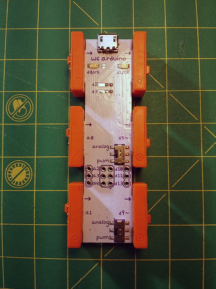
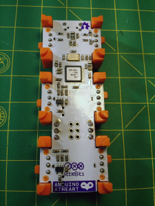
- Arduino Module – Front
-
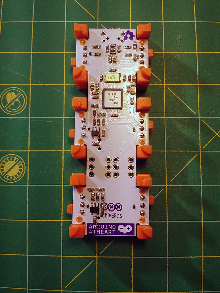
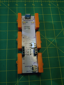
- Arduino – Rear
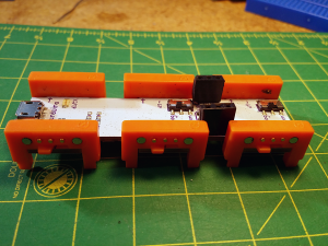
As with all Bit Modules, the littleBits Arduino module has its inputs on the left side, and its outputs are on the right.
The bitSnap inputs, in order from top to bottom, are:
- Digital IN & Serial IN (D0/RX),
- Analog/Digital IN (A0), and
- Analog/Digital IN (A1)
The bitSnap outputs, in order from top to bottom, are:
- Digital OUT & Serial OUT (D1/TX),
- Digital PWM OUT (D5~), and
- Digital PWM OUT (D9~)
These inputs and outputs are enough for many people, but for more advanced users, littleBits offers additional connectivity as the diagram below illustrates:
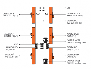
source: littlebits.cc
There are two pads (not through holes) at the top of the module for digital I/O. These correspond to D2 andD3 of the ATmega32U4 chip that is the heart, or appropriately, brains of the Arduino. These pins are used for the I2C communication protocol. D2 is for SDA and D3 is for SCL. The pads are meant to have the pull-up resistors necessary for I2C soldered to them. They can also be used as digital general-purpose input output, GPIO, but since I’m looking for through holes to connect headers, and may want to use I2C in the future, I am going to leave these pads alone for now.
At the bottom of the module, in the middle, are through holes for making an ICSP, in-circuit serial programming, connection. Again, not really relevant to this post, but the six holes correspond to MOSI, MISO, SCK, RESET, VCC, and GND. ICSP is more generically a type of SPI or serial peripheral interface. Using an AVR programmer, the bootloader of the ATmega32U4 chip can be written to. More about this in a later post, though.
The through holes of interest to me right now are at the bottom of the module, to the left and right of ICSP holes. The holes on the left correspond to three analog GPIO pins: A2, A3, and A4, while the three on the left offer up three digital GPIO connections via pins D10, D11, and D13. These *are* the pins I am looking for.
Connecting female headers to these holes is a straight-forward exercise in soldering, which this post is not meant to be about, so I’ll just provide some pictures to document how it went.
-
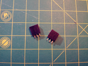
- The Headers
-
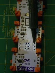
- Heating the pad and header pin.
-
- Getting ready to solder.
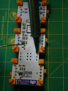
-
- One down. Five to go.
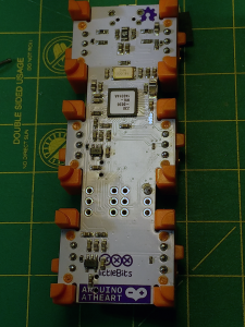
-
- All six soldered.
-
- The finished product.
Now that this is out of the way, and I have my homegrown Perf Module, I am ready to tackle some more interesting projects with the littleBits system. Stay tuned.