
DIY littleBits Perf Module
The littleBits modular electronics system is great for rapidly prototyping electronics circuits, but what happens if you want to use an element, switch, sensor, actuator, etc., for which a module does not exist? Fortunately, littleBits provides three different solutions for the problem. Two of these are ready to go modules: the Proto Module and the Perf Module, while the third are just the connectors you need to roll your own module: the BitSnaps.
Proto Module
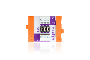
source: littlebits.cc
When the engineers at littleBits want to create a new module to add to the arsenal, this is what they start with. They’ve since released it to the public as a stand-alone module and also as part of their Hardware Development Kit (HDK). The Proto Module provides easy, direct access to the vcc, ground, and signal lines. Many littleBits hackers use this bit to create their own modules, but another very common use is as an access point for measuring the signal at a specific spot in the circuit or as a junction point to other, external instrumentation.
Perf Module
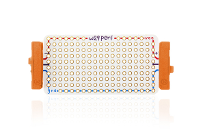
source: littlebits.cc
When your prototyping needs are more demanding than what the Proto Module is meant for, you can always use the Perf Module. This bit consists of a standard 0.1″ (2.54mm) perfboard with power and ground busses running its length. Like all bits, either end is capped with a BitSnap allowing the module to be inserted easily anywhere in your circuit that your heart desires. You can build your own intermediate circuit by soldering sensors, actuators and other components directly to the perfboard and tying them into the provided busses.
Note: My goal (as outlined below) was to build something similar to this module.
BitSnaps
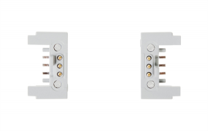
source: littlebits.cc
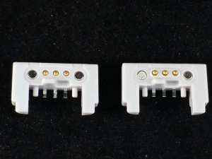
If you really want to rough it, you can start start your prototyping with a pair of these. The BitSnaps Modules are nothing more than the color-coded, magnetic connectors that bookend all littleBits modules. They come in two varieties: male, which are on the input side of the module and female, which act as the modules output. The type of a regular module (power, input, wire, output) is designated by the color the module’s BitSnaps. When purchased individually, the BitSnaps are not colored, but littleBits includes stickers designed for the BitSnaps so that you can mark the functionality of your own creations using their standard system. Tiny leads corresponding to vcc, ground and signal are meant to be soldered directly to a printed circuited board.
DIY Perf Module
I wasn’t lucky enough to find a littleBits Proto Module or Perf Module during my weeks-long buying spree facilitated by Radio Shack’s bleed out, but I did manage to get my hands on a pack of BitSnaps.
BitSnaps
I admit that I wasn’t giving too much thought to creating my own modules when I grabbed these. The price was right, and they were just one of those “better safe than sorry” impulse buys. Once I started tinkering with the littleBits Arduino Module that was the centerpiece of the Arduino Coding Kit I had snagged, I knew immediately that I needed a painless way to add my own, non-littleBits components as inputs and outputs to the Arduino Module. The BitSnaps were clearly my solution. I was safe (not sorry).
At this stage while I am still getting my feet wet, I would strongly prefer to prototype on a breadboard than face the relatively more permanent option of soldering components on a perfboard. The BitSnaps’ leads, however, readily lend themselves to being soldered on to a circuit board. Given more time and harder brainstorming, I may still come up with an easy solution for using BitSnaps with a breadboard, but for now I thought my best bet was to see if I could build my own Perf-like module. I figured that if I added headers on the perfboard for power, ground, and signal that I could still use a small breadboard much as I do with the handful of Arduino protoshields I regularly work with.
The first thing I did was to choose a perfboard. While I won’t go overboard with details, I do want share that the first board I chose was microtivity IM414 double-sided prototyping board:
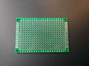
In general I really like these. They are my go-to board when I need a small circuit board for prototyping. To make a long story short, I started with one of these boards and followed the same steps I will outline shortly. I was defeated in the end by an all too common foe: the relative difficulty of connecting pads on a perfboard without messing up any previously installed components or connections. I knew I wanted to add headers as well as both power and ground busses. By the time I had everything wired up, I found that I had accidentally melted the plastic feet of the BitSnap connectors.
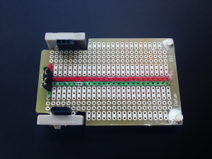
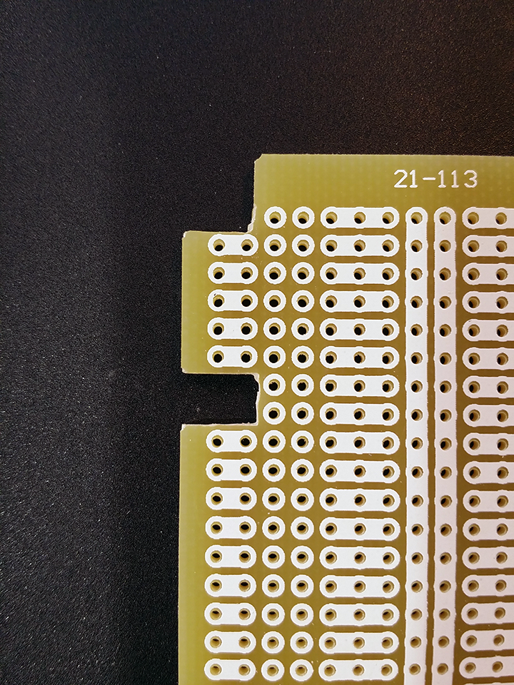
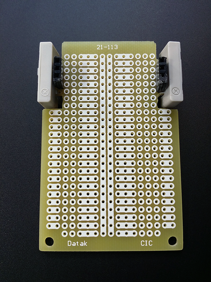
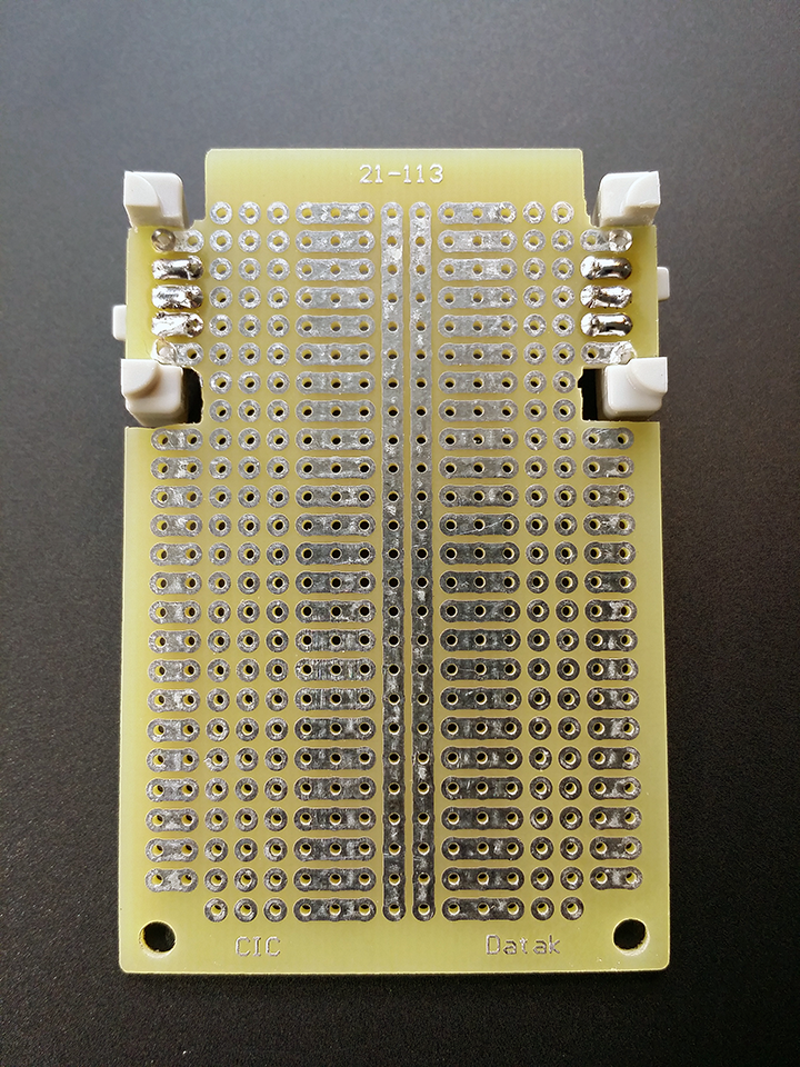
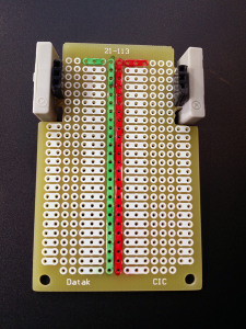
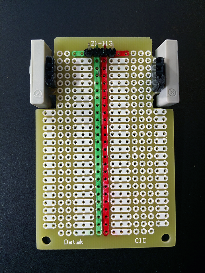
Rather than start over with the same board and hoping that I wouldn’t be as careless as on my first attempt, I chose instead to find a more appropriate board. After several minutes of digging and cursing I found just what I was looking for in the RadioShack Make: It Component Kit 2, yet another close-out goody that I have as of yet not blogged about. It is a 47 x 72mm board with a pair of busses running up its center as well as partial rows of interconnected pads much like in a breadboard.
-
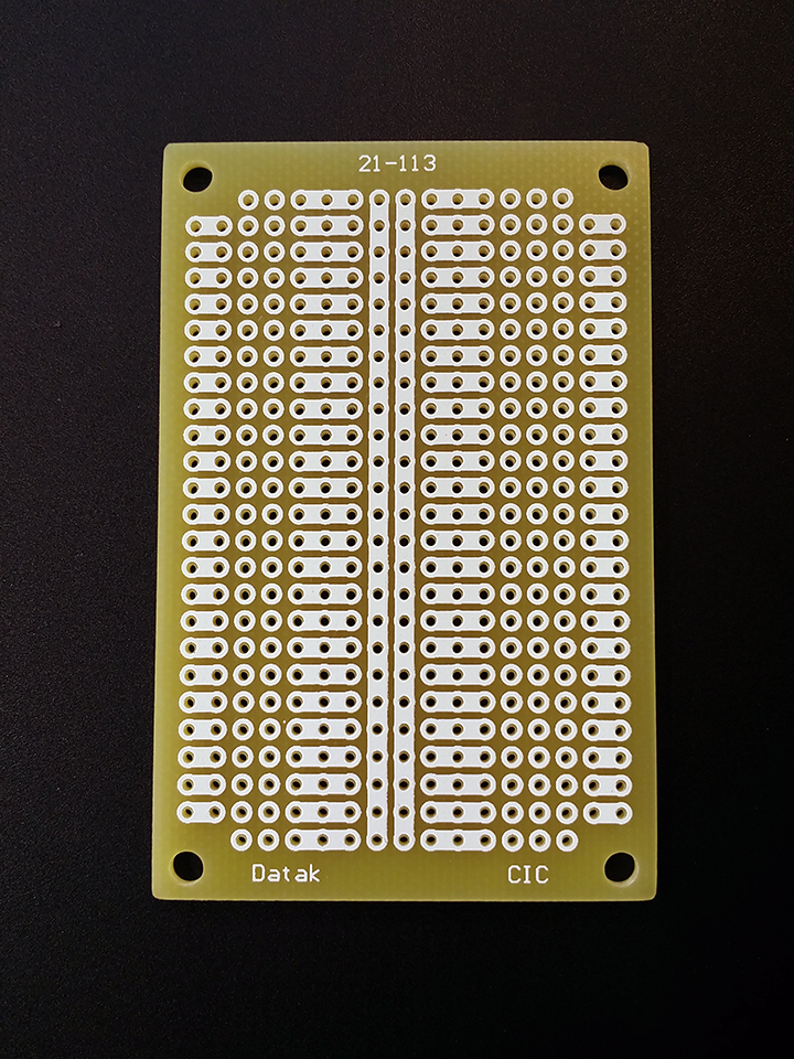
- Front
-
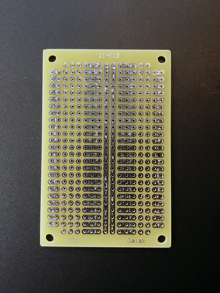
- Rear
Now, where to connect the BitSnaps? The first two pads in every row are connected but not to the third. This looks like a good place since it will allow me to connect a header easily. I know that I need to use five holes length wise for attaching the BitSnap: the three in the middle need an electrical connection for power, signal, and ground and the two on either end for a physical connection the BitSnap’s plastic support posts. With that in mind, I grabbed my handy Dremel and cut out some notches to make room for the BitSnap, and drilled out the two end holes so that the support posts would fit through:
-
- Step 1
-
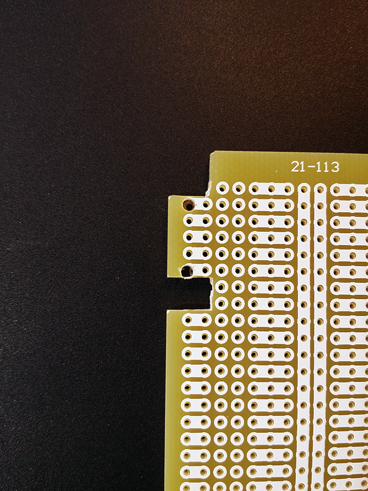
- Step 2
Admittedly not my cleanest work, but it will do. I then repeated the process on the opposite side of the board and wiggled the BitSnaps into place to check the fit:

Step 3
Satisfied that the BitSnaps fit nice and tight, I removed them and set them aside so they didn’t get in the way as I soldered on a triple female header for each BitSnap. Not much to say about this step, so here is the end result:
-
- Step 4 – Front
-
- Step 4 – Back
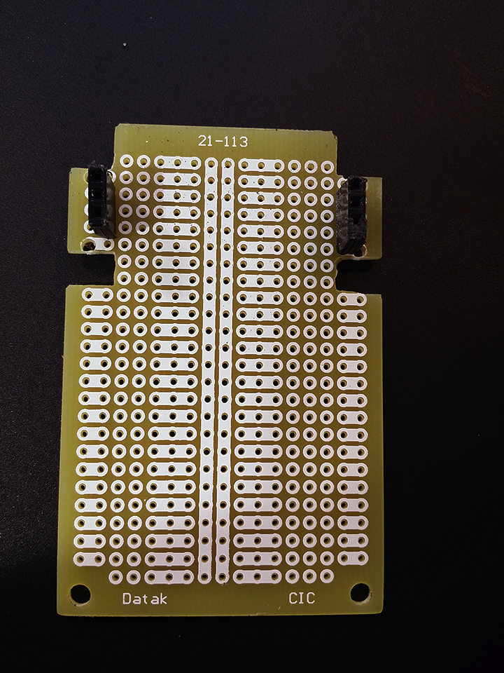
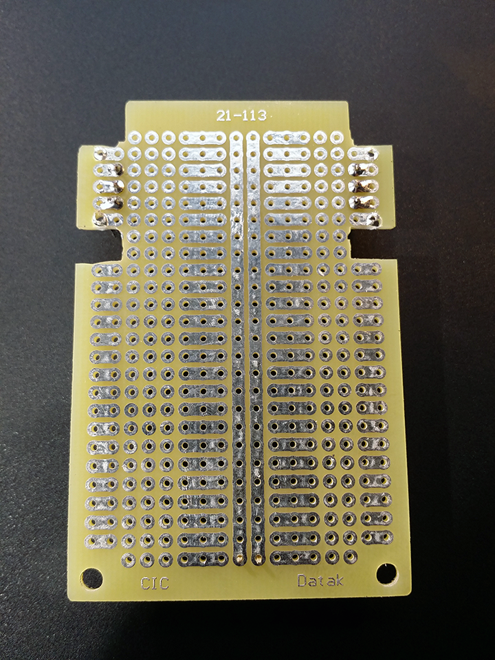
With the headers in place, I reattached the BitSnaps and soldered their leads to the perfboard:
-
- Step 5 – Front
-
- Step 5 – Back
At this point I thought a quick sanity check was a wise idea. I didn’t want to get too far along before having to track down a short circuit or other problem. Then it occurred to me that I hadn’t yet bothered to figure out what the leads on the BitSnap actually were. That seemed fairly important, too, and a quick visit to the BitSnaps product page set me straight:
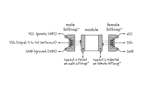
source: littlebits.cc
Well, there you go. That is simple enough. First I take a look at the voltage drop at the input header:
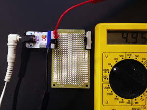
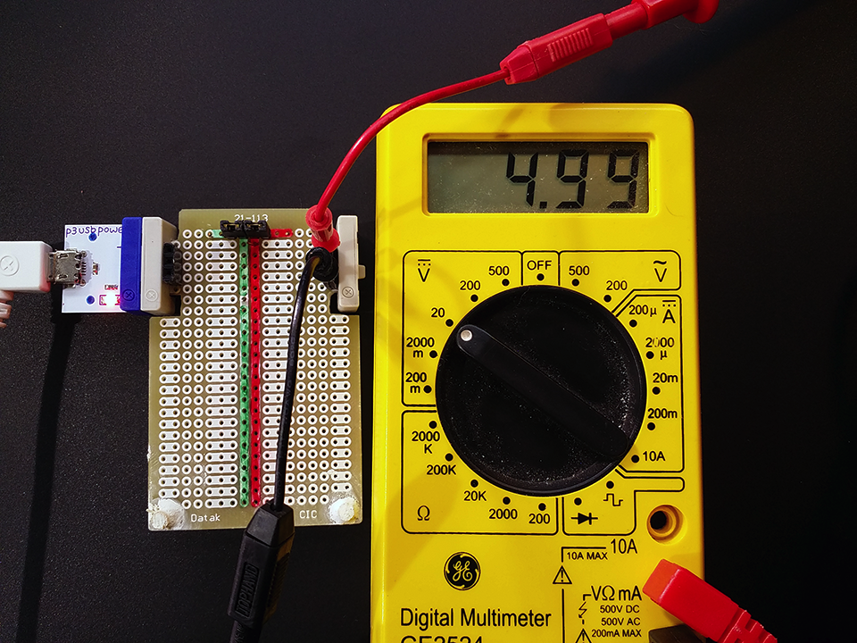
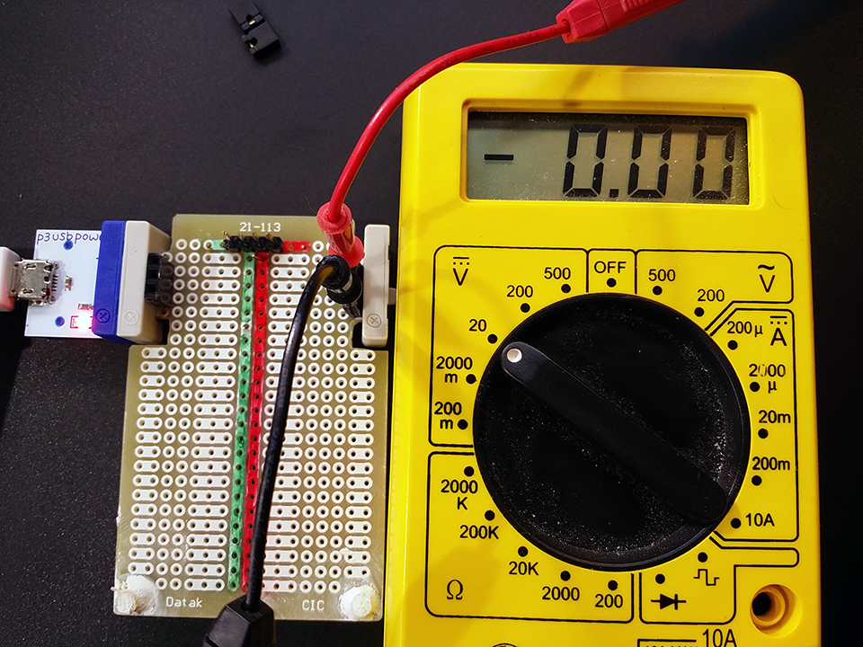
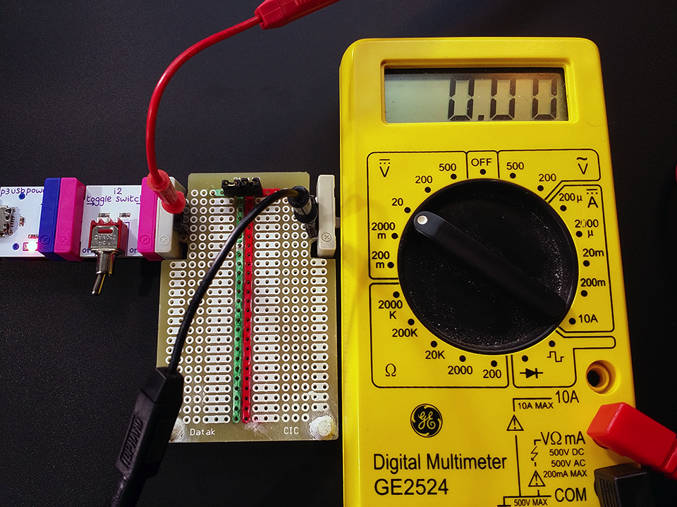
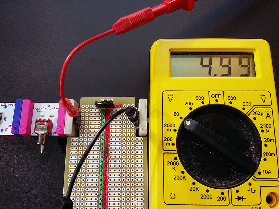
I tested the voltage on the output side, but apparently forgot to take a picture. You’ll have to take more word that the other side checked out fine as well. Now, I’ll take a look at the input signal. I’ve thrown a toggle switch in between the power module and the board so I can turn the incoming signal, which should be ~5V, on and off:
-
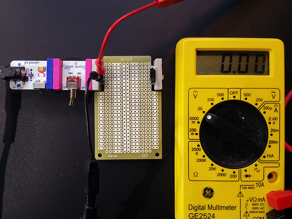
- Off
-
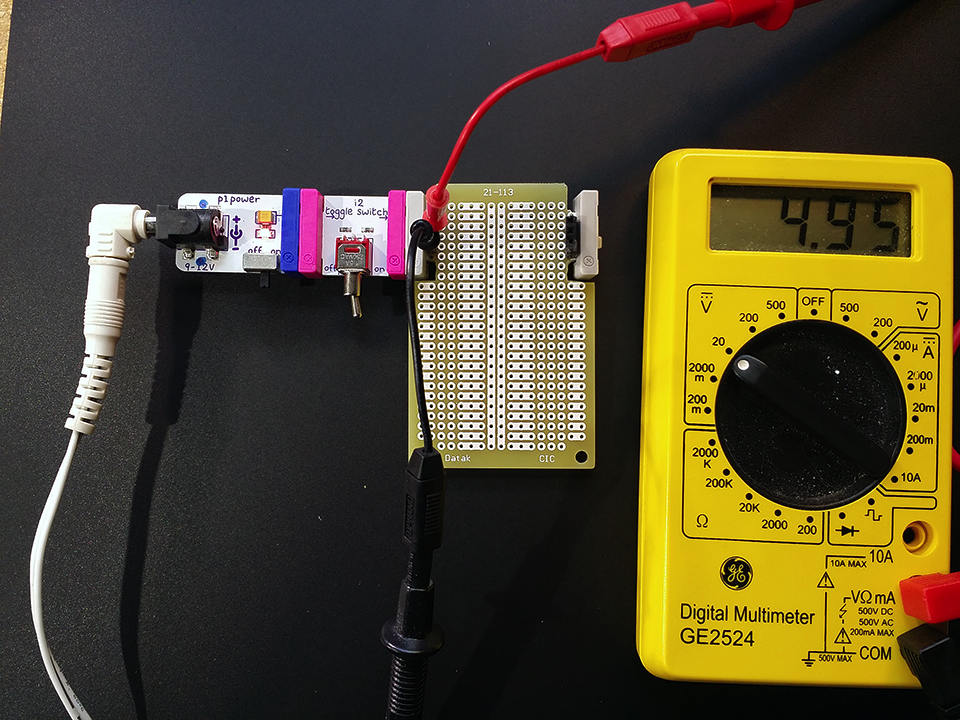
- On
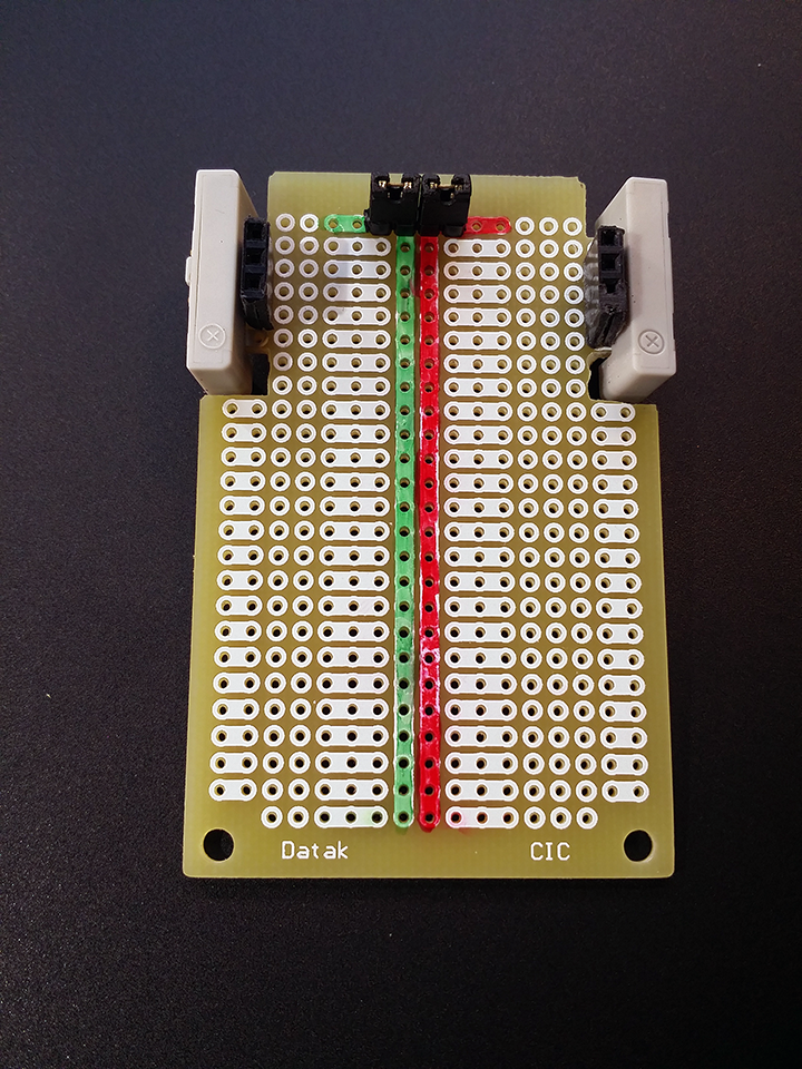
Everything looks good. Time to wire up the busses. The first thing I did was to take a Sharpie (two actually) to the front of the board just so I could remember which bus was which.
Step 6
I decided to extend each bus at the top because I wanted to add jumpers so that I could disconnect power, ground, or both if the situation ever arose. The top (colored) row on either side of the buses are not electrically connected to the vertical bus columns. Hoping to avoid the inter-pad soldering I knew was coming for as long as possible, I soldered the aforementioned jumpers in place first.
-
- Step 7 – Jumpers Open
-
- Step 7 – Jumpers Closed
This feels like cheating, but I’m not going to cover every power/ground connection I ended up making, but instead will just provide a picture and hope that the paths are easy enough to follow.
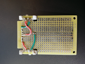
Step 8 – All wired up
This next part is not nearly as aesthetically pleasing as I hoped, and my goals were low, but I epoxied some small dowels on the opposite end of the board so that it would sit level.

Step 9
Ugly or not, I just care about how well it works. Fortunately she passed all tests with flying colors.
-
- Power Test – On
-
- Power Test – Off
-
- Signal Test – Off
-
- Signal Test – On
That’s all I’ve got for now. This post turned out to be considerably longer than I thought it would. I anticipate that I will add some small velcro tabs on top so that I can temporarily attach a small breadboard on top of the perfboard for less destructive tinkering. I found this works pretty well with the Arduino protoshields anyway.
Expect to see this homegrown littleBits module in upcoming posts, unless I totally screwed it up in a way I haven’t discovered yet. In that case, I’ll pretend I have no idea what you are talking about if you ever ask me about it.
1 comment
Hi how do i solder an audio input jack to the perf. Im confused on what to connect to.