

GE2524 Multimeter
Question: Based on your previous post regarding voltmeters and internal resistance, I can safely assume that an ammeter must also have some internal resistance. What effect does this resistance have on current measurements, and what resistance value would minimize any error it introduces to the reading?
Answer: It is indeed true that an ammeter must have some internal resistance because like a voltmeter, it must draw current from the circuit in order to make its measurement. The similarities between ammeter and voltmeter internal resistances end there, however.
Ammeter
 Symbol |
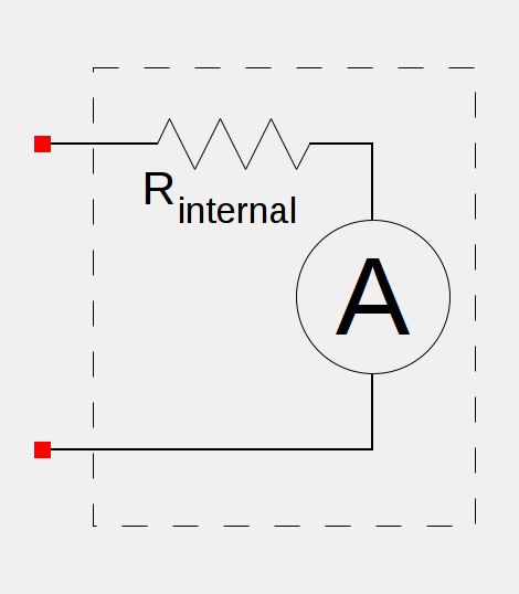 Real Model |
So, how does the internal resistance of an ammeter affect its readings?
Again ignoring all other factors, the internal resistance of an ammeter will cause it to read a smaller current than what is actually passing through the portion of the circuit it is measuring. To see why, we just need to examine a very simple circuit:
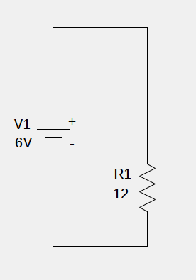
This circuit consists of a 6 volt battery (V1) and a 12  resistor (R1).
From Ohm’s Law we know that:

Rearranging, substituting our values, and solving for the current i:


So we know that there is  of current flowing through our simple circuit. When we measure the current with our ammeter, we find it measures a little lower. If we look at our circuit with the ammeter probes attached, the reason for this becomes obvious.
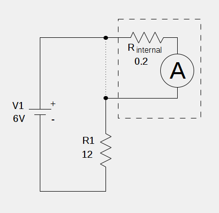
Ammeters must be placed in series with the branch of the circuit whose current they are measuring. In the image above, the dotted line represents the portion of the circuit, likely wire, that is no longer connected between the probes. If the wire were left in place, the ammeter would be shorted out.
Now we can see that the total resistance of the circuit has changed. It is no longer  but now because is in series with the internal resistance of the ammeter,
  , the total resistance of the circuit becomes:


Solving for the current i again:


This is a 2% difference from the true value which we know to be  . This difference may not be a big deal for many applications, but at the end of the day,
  is not .
In order to minimize the effect of the ammeters internal resistance, we need it to contribute as little as possible to  so it should be as small as possible. Realistically, the error becomes much less significant as the regular resistance of the circuit gets larger. I chose
  because it makes the error more obvious (and also makes the math easy), but when the circuit resistance is on the order of kilo- or megaohms, the error rapidly drops.
So ends another chapter in our investigation of how internal resistance of one of a multimeter’s components affects its readings. I guess I can’t avoid writing about ohmmeters now. Look for one more article in this series before long.