

GE2524 Multimeter
Question: Does a voltmeter have any internal resistance, and if so, what, if any, affect does it have on voltage readings?
Answer: Even if you have no electrical experience at all, I would hope that your answer to the first part of the question was, “yes.” Otherwise this would turn out to be an incredibly short post.
To do its job, a voltmeter must draw current from the circuit it is measuring. In order to avoid that whole no resistance/infinite current issue and to draw as little current as possible, a voltmeter must have some internal resistance.
Voltmeter
 Symbol |
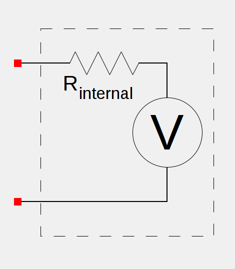 Real Model |
But how does this internal resistance affect it’s readings?
Ignoring all other qualities of the voltage meter, the meter’s internal resistance will cause it to register a smaller voltage across the circuit elements being measured than is actually the case. Consider the following simple circuit:
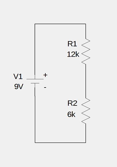
This circuit consists of a 9 volt battery (V1) and a 12 k resistor (R1) and a 6 k resistor (R2) in series. To illustrate the effect of the voltmeter’s internal resistance on measurements, we will focus on the voltage drop across R1.
Resistors in series create a simple voltage divider, so if you know the voltage divider equation it’s pretty trivial to calculate the voltage across R1. If you don’t know it, we can derive it pretty quickly.
Ohm’s Law tells us that for a purely resistive circuit:

Since R1 and R2 are in series,  . Therefore:

Since the circuit is a simple loop, the current i is the same through all of the elements. Solving the above for i, we get:

Ohm’s Law also gives us the voltage across R1:

Substituting in our current equation gives us the voltage divider equation for R1:

Substituting in the values for our sample and solving:


When we attach our simplistic “real model” of a voltmeter to measure  , our circuit now looks like:
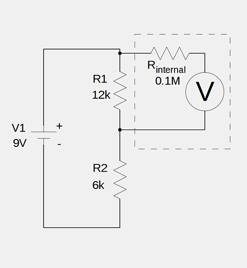
Now we no longer have a simple voltage divider since  is in parallel to
  , the internal resistance of the voltmeter. Since these two are in parallel, we can calculate their combined resistance, which I’ll call
  , like so:

Substituting our values:


 is not quite the
  resistance of R1 alone. Since is in series with R2, we can modify the voltage divider equation to find the voltage across . (Reminder:
  is really what we take to be V1.)


So, we measured 5.77 v instead of 6 v, a 3.8% error. This difference may not be a big deal in many instances, but in some applications the measurement error could be critical.
Of course, the size of the error is dependent on many factors. In our little circuit alone, it depends on the value of V1, R1, R2 and . How can we make sure that we minimize the error?
Minimizing the Error
First, let’s define a function describing the error. We’ll assume all of the circuit elements and their properties are static, and the only factor we can control is , the internal resistance of the voltmeter. It seems pretty obvious that in order for us to minimize the error, we need , the equivalent resistance of R1 and in parallel, to be as close to R1 by itself as possible.
So, we define the error as:

This is the function we want to minimize, but unfortunately it does not explicitly contain the variable we can control: . We can, however, rewrite , in a form that gives us what we need.
As we said above:
We can rework that equation into one that some readers may be more familiar with for calculating resistors in parallel.


We can now substitute this back into our error function and simplify it.


Finally we come to the error function we wish to minimize:

Examining this equation, it is easy to see that the larger gets, the smaller  gets. As approaches infinity, approaches
  .
.
In other words, in order to ensure your voltage readings are as accurate as possible, your voltmeter needs to have an internal resistance that is as high as is practical. If I get around to it, I may show in a later post that if your voltmeter is actually a multimeter, internal resistance plays an important role in accurately taking other measurements as well.
12/27/14 Update: Read about internal resistance and ammeters here.
1 comment
The above math for fig. 1 can be simplified thus: R1 and R2 are in series so R1+R2= 18K (Rt). R1=12K so the voltage drop ratio is R1/Rt or 12K/18K or 2/3 of the applied voltage which is 9V. 2/3 of 9V is 6V. This works because the current through
both resistors is the same.